QuickTime 3 Reference
Basically, ink objects exist to specify two important characteristics of a shape: its color and the transfer mode to draw it with. Transfer modes are described here.
Transfer modes specify how a shape's color is transferred onto a device. The color of a shape to be drawn (the source color ) interacts with the existing color (the destination color ) on the device it is drawn to. The color that results from that interaction is called the result color. The result color is the color of the destination after the drawing occurs.
Note that colors from different color spaces can be used. The source and destination colors are converted to the transfer mode's color space, and the resulting color is then reconverted to the destination color space.
Transfer modes can be specified by type, also called component mode. Transfer mode types in QuickDraw GX are called component modes because QuickDraw GX allows each color component to have its own transfer mode type. In RGB color space, for example, the red component of the color may be drawn with a different transfer mode type than the blue component.
QuickDraw GX supports several conceptual categories of component modes:
The characteristics of and most typical uses for the component modes within each category are summarized in the following subsections.
Even though QuickDraw GX supports 18 different component modes, most applications in most situations need only one, an arithmetic mode called copy mode. In copy mode, the source color completely replaces the destination color. Copy mode is the default transfer mode in QuickDraw GX; therefore, you need information about other transfer modes only if you want them for special effects.
In arithmetic transfer modes, the numerical values of source and destination for a color component are combined arithmetically to determine the result value for that color component. In most color spaces, a color component value can vary from 0 (no intensity) to 0xFFFF (maximum intensity). You can also use the constant gxColorValue1 to represent maximum intensity (0xFFFF).
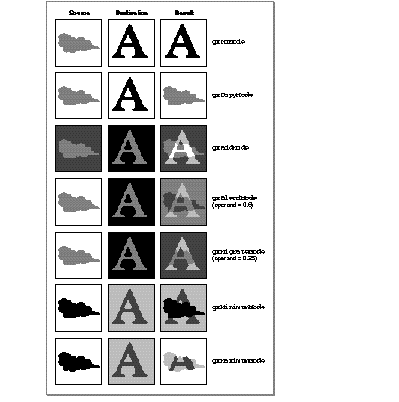
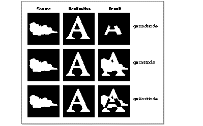
Figure 39 shows examples of drawing with the arithmetic transfer modes. In each case, the source image (left) combines with the destination image (center) to produce the result image (right). You can think of the images either as two bitmaps, or as two source shapes (cloud and background) that are drawn over two destination shapes (letter and background).
Each example shows how transfer mode affects drawing within a single color component (reflected as shades of gray in the figure, where black equals 0 and white equals 0xFFFF). The constant that specifies the transfer mode type is shown to the right of each example. Note also that two of the arithmetic transfer modes use an operand, a numerical value that affects the outcome of the transfer-mode operation.
Figure 39 Arithmetic transfer modes
The constants that define transfer mode type are defined in the gxComponentModes enumeration. The arithmetic modes have the following values and meanings:
|
No mode. No transfer occurs. For this component of |
||
|
Copy mode. The source color component is copied to |
||
|
Add mode. The source color component is added to |
||
|
Blend mode. The result is the average of the source |
||
|
Migrate mode. The destination color component is moved toward the source component by the value of |
||
|
Minimum mode. The source component replaces the |
||
|
Maximum mode. The source component replaces the |
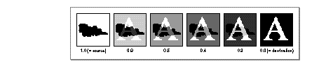
The operand parameter is used by blend mode to specify the ratio of source and destination component. It is used by migrate mode to specify the step size by which the destination component moves toward the source component. Figure 40 shows examples of the result of drawing with blend mode, using several different values for the operand.
Figure 40 Blend example with different operand values
The highlight transfer mode is used for highlighting in color applications. It is most commonly used to draw (and clear) a colored rectangle around a selection, without altering the color of the item or items selected. In text, it gives the effect of drawing over the letters with a highlighting pen.
Like some of the arithmetic transfer modes, highlight mode uses an operand to control the outcome of the highlighting operation. Highlight mode operates by replacing the source color with the operand color, and the operand color with the source color, in the destination.
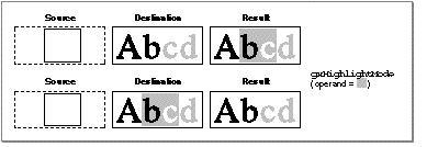
The upper row of images in Figure 41 shows a simple example of the application of highlight mode. The operand value is represented with shading rather than as a number, to illustrate how its color affects colors in the image. The source shape is a white rectangle that is drawn over the two middle letters in the destination image. (The gray letters in the line of text in the destination image represent the same color-component value as the operand, and the white area around the letters in the destination represents the same color-component value as the source.)
Figure 41 Highlight transfer mode
Note that black in the destination is unaffected, whereas white becomes gray and gray becomes white. A single constant specifies highlight mode, with the following value and meaning:
|
Highlight mode. The source component and operand component are swapped in the destination. Other components in the destination are ignored. |
In highlight mode, the source color can be thought of as the "background" color that is to be highlighted, and the operand color is the color of the highlighting pen. As the lower set of images in Figure 41 shows, redrawing a highlighted selection causes the source and operand colors to swap once more, effectively removing the highlighting.
The operand for highlight mode is a normal color component value that varies from 0 (no intensity) to the maximum intensity permitted for that component (normally 0xFFFF , or gxColorValue1 ).
QuickDraw GX applies highlight mode only if all components in the color space specify it. An error occurs if some components specify highlight mode and others do not.
In Boolean transfer modes, the result value for a color component is determined by bit operations performed on the source and destination component values. Boolean transfer modes are most common in black-and-white drawing; in any bit depth other than 1, they yield results that can be difficult to predict because they depend on the states of the individual bits in each color-component value.
Figure 42 shows examples of drawing with the Boolean transfer modes at a bit depth of 1. In each case, the source image combines with the destination image to produce the result image. In these examples, black represents a bit value of 0 (clear), and white represents a bit value of 1 (set). The constant that specifies the transfer mode type is shown to the right of each example.
Figure 42 Boolean transfer modes (1-bit depth)
The Boolean modes have the following values and meanings:
Even though they are most easily explained in terms of single-bit depths, Boolean modes are not restricted to 1-bit drawing. They can be used with any kind of color values.
In pseudo-Boolean transfer modes, the result value for a color component is determined by normalizing the source and destination values and performing a simple arithmetic operation, to achieve consistent and predictable results analogous to 1-bit Boolean operations.
Figure 43 shows examples of drawing with the pseudo-Boolean transfer modes. In each case, the source image combines with the destination image to produce the result image. The constant that specifies the transfer mode type is shown to the right of each example.
Figure 43 Pseudo-Boolean transfer modes
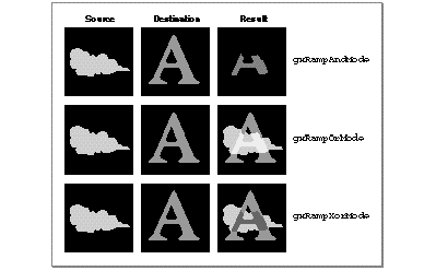
The constants for the pseudo-Boolean component modes have the following values and meanings:
Note that the pseudo-Boolean and Boolean modes are similar in several ways:
The difference between the pseudo-Boolean and Boolean modes is that, for multi-bit pixel depths, the results for gxRampAndMode , gxRampOrMode , and gxRampXorMode are predictable and vary smoothly and continuously with component intensity. For 1-bit depths, these modes are identical to their Boolean equivalents.
The pseudo-Boolean modes are commonly used as component modes for alpha channels in color spaces that have an alpha channel. For more information, see "Alpha-Channel Transfer Modes" .
Several QuickDraw GX color spaces ( gxRGBASpace , gxARGB32Space and gxGrayASpace ) have an alpha channel. This is an additional color component that controls the opacity or transparency of a color. For example, a red pixel in a source image can be completely opaque, in which case it typically retains its red color when drawn over a blue pixel in the destination image. Or, the pixel can be completely transparent, in which case it typically loses all its color and turns totally blue when drawn over a blue pixel. Or, it can have an opacity of, say, 0x7FFF (50%), in which case it typically turns magenta when drawn over a blue pixel.
Alpha channel values can be used to allow parts of one image to show through "holes" in another, to show translucency in objects that are drawn over other objects, and to perform anti-aliasing (smoothing of jagged edges) by giving feathered, semi-transparent borders to opaque objects.
When assigning transfer modes to colors with an alpha channel, you typically use two different kinds of modes:
This section describes how the different modes within each category work to give you the results you want.
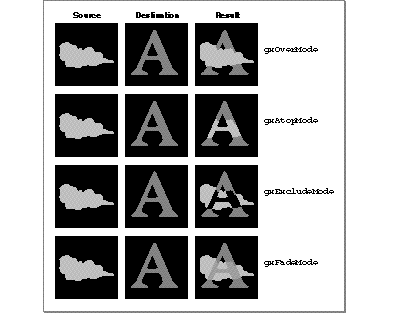
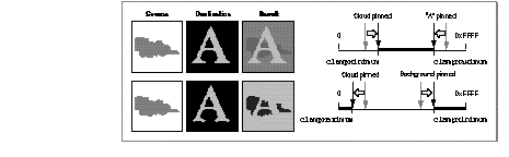
Figure 44 shows examples of how values for a color component might be calculated, given a source image and a destination image consisting of objects (or pixels) that differ in opacity. In each example, the source image (an opaque, light gray cloud against a transparent black background) combines with the destination image (an opaque, dark gray "A" on a transparent black background), to form the result image. The constant that specifies the transfer mode type is shown to the right of each example.
Each example shows how the alpha-channel transfer mode affects drawing within a single color component. The mode takes into account not only the source and destination color components, but the source and destination opacities as well.
Figure 44 Alpha-channel transfer modes
The constants for the alpha-channel component modes have the following values and meanings:
As Figure 44 shows, the gxOverMode mode is similar to the arithmetic transfer mode gxCopyMode , except that it allows for transparency in the source image. Likewise, the gxAtopMode mode is similar to gxCopyMode , but it preserves the transparency of the destination image by clipping the opaque source to the destination image. The gxExcludeMode mode is somewhat like the Boolean transfer mode gxXorMode , in that opaque parts of each image appear only where the other is not opaque. The gxFadeMode mode is like the arithmetic gxBlendMode , except that the operand that controls the blend ratio is determined by the relative opacities.
Note that the images shown in Figure 44 are very simple and their opacities are either 0 (completely transparent) or gxColorValue1 (completely opaque). Because an alpha component can have a wide range of partial opacities, very sophisticated translucency and color-blending effects are possible, as well as the simple masking effects shown here.
The exact formulas for determining result color are the following. In these formulas, sA = source alpha-channel value; dA = destination alpha-channel value; sC = source color-component value; dC = destination color-component value; and rC = result color-component value.
rC = (sA x (sC - dA x dC) + dA x dC) / (sA + dA - sA x dA)
rC = dC + sA x (sC - dC)
rC =    (sA x sC + dA x dC- sA x dA x (sC + dC)) /

        (sA + dA - sA x dA)
rC = sA x sC + dA x dC / (sA + dA)
For calculating the result value for the alpha channel itself, you typically use one of the arithmetic or pseudo-Boolean transfer modes presented in the previous sections--one that takes into account only the source and destination opacities. Figure 45 shows typical modes used and their effects on opacity, using the same images is those presented in Figure 44 . In this figure, black represents complete transparency and white represents complete opacity. (If alpha-channel values between the two extremes existed in these examples, they would be shown in shades of gray.)
Figure 45 Typical modes used to determine result opacity for the alpha channel
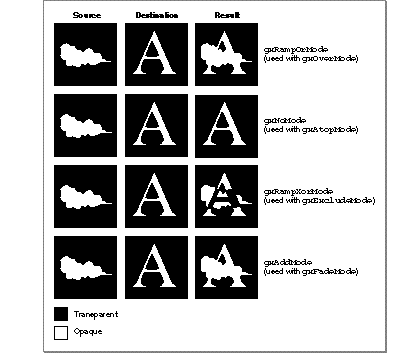
Note from Figure 45 that the mode you use to determine the result opacity of the alpha channel usually depends on what alpha-channel mode you use to get color-component values:
When converting a color from a color space that does not have an alpha channel to one that does, QuickDraw GX sets the alpha channel intensity to maximum (opaque). When a color is converted from a color space that does have an alpha channel to one that does not, the alpha channel is lost.
Two common applications for alpha-channel colors involve making objects or images partially opaque to give a translucent effect, and smoothing jagged edges on objects drawn at low resolution.
You can create a bitmap in which the alpha-channel values of the pixels vary smoothly in one or more directions, thus creating a transparency ramp that allows the destination image to show through the source image to varying degrees across the bitmap. Color Plate 2 at the front of this book, for example, shows the kind of effect that can be achieved with a simple alpha-channel ramp.
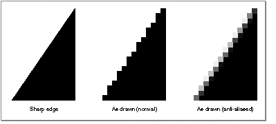
The smoothing of jagged edges on displayed objects is called anti-aliasing. You can perform anti-aliasing by modifying the alpha-channel values of the pixels surrounding the edges of an opaque object. You make an individual pixel more or less opaque, based on the proportion of that pixel that the object is computed to cover.
In Figure 46 , for example, the left image shows the computed position of the edge of a shape in a bitmap. The center image shows how that edge is displayed normally, given the resolution of the bitmap. The right image shows that edge as it might be displayed with anti-aliasing applied. The apparent jaggedness is decreased because pixels near the edge allow the background to show through to varying degrees.
The space field in the transfer mode structure specifies the color space the transfer mode calculations take place in. This space does not need to be the same as the color space specified by the ink's color, or the destination color space as specified by the view port or view device with which the ink is associated. The source and destination colors are converted into the color space that provides the context for the transfer, and the resulting color is then reconverted to the destination color space. Keep in mind that all transfer mode computations take place in the transfer mode's color space.
You needn't convert color values among different spaces yourself in order to use a different transfer mode. The transfer mode operation automatically converts colors from the ink's color space and the view device's color space, manipulates them, and then converts the result color back to the view device's color space for drawing. In creating shapes, you can work in whatever color space is convenient for you; when drawing, you can use any transfer mode color space you want; and neither color space need be the same as the color space used by the view device to which you are drawing.
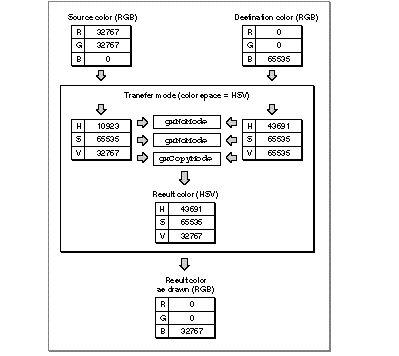
Figure 47 , for example, shows a source color in RGB space as specified in an ink object, a destination color in RGB space as specified by a monitor, and a transfer mode color space of HSV, as specified by the application. The component modes selected mean that the hue and saturation of the destination are preserved, but the value (lightness) of the source is maintained. QuickDraw GX automatically performs all necessary conversions.
Figure 47 Automatic conversion of color values during a transfer mode operation
The transfer mode color space defines how many components are required to perform the transfer mode operation. Monochromatic (grayscale) color spaces require only one component to be filled out. Alpha-channel spaces and CMYK space require four components to be filled out. All other spaces require three components to be filled out.
Choosing a different color space can radically affect the behavior of a transfer mode. For example, if your transfer mode uses RGB space, and you have specified gxCopyMode for the component mode of component[0] and gxNoMode for the other components in the transfer mode structure, drawing will transfer only the red component of your source image to the destination, and leave the blue and green components of the destination as they are. If you then change the transfer mode color space to HSV and redraw, all hues in your source image will be transferred to the destination, but with the brightnesses and saturations of the original destination image.
Transfer mode operations allow you to specify limits on the acceptable input values for the source or destination color, and on the acceptable output values for the result color. For example, in converting CMYK color to RGB, you may wish to limit the intensities to values that can be displayed without oversaturating the phosphors on a monitor's screen. Or, to create a special effect, you may want to draw only the extreme light and dark portions of an image, leaving out its midrange entirely.
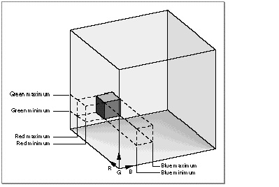
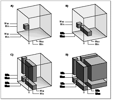
Each color component in the component field of the transfer mode structure can have a maximum and a minimum permitted value. The permissible ranges can be interpreted as shown in Figure 48 . In the figure, the large cube represents all of RGB space; the small cube represents one possible example of the limits that could be imposed on allowable values for all three components.
Figure 48 Maximum and minimum color-component values in RGB space
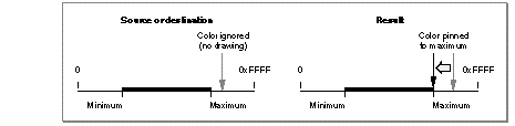
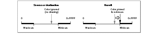
In the case of source and destination colors, color values outside the range of acceptable values (that is, outside the small cube in Figure 48 ) are ignored; if any single component value is outside of its acceptable range, no drawing occurs at all for that color. In the case of the calculated colors that result from a given transfer mode operation, color values outside of the acceptable range are pinned to, or moved so that they don't exceed, the nearest acceptable value (the closest edge of the small cube). See Figure 49 .
Figure 49 How minimum and maximum color limits affect drawing
For a given component, the maximum value for a color limit can be either greater or smaller than the minimum. If the maximum is less than the minimum, only the extreme color values (that is, values outside of the small cube area in Figure 48 ) are allowed. See Figure 50 .
Figure 50 How reversed minimum and maximum color limits affect drawing
Each of the components in a color space can have its limits set entirely independently of the others. Figure 51 shows the effects of reversing, in turn, the maximum and minimum values for each of the three axes in RGB space.
Figure 51 The effects of reversing maximum and minimum in a color space
Where the words Min and Max are bold in Figure 51 , the minimum is greater than the maximum. Refer to Figure 48 for the positions of the color axes on the RGB cube in this figure:
The sourceMinimum and sourceMaximum fields in a color component's gxTransferComponent structure define the allowable range of values for source color in that component. Color values outside of the range cause no drawing to occur. If sourceMaximum is less than sourceMinimum , the range allowed consists of values less than sourceMaximum or greater than sourceMinimum . Figure 52 shows the effect of sourceMinimum and sourceMaximum on drawing using blend mode.
Figure 52 The effect of source color limits on drawing
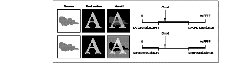
Note in Figure 52 that, when sourceMinimum is less than sourceMaximum , only the cloud in the source image is within the source limits, so only the cloud is blended with the destination image to create the result. Conversely, when sourceMaximum is less than sourceMinimum , the cloud in the source image is outside the source limits, so it is the only part of the source that is not blended with the destination image when creating the result.
The deviceMinimum and deviceMaximum fields in a color component's gxTransferComponent structure define the allowable range of values for destination color in that component. Destination color values outside of the range cause no drawing to occur for that color. If deviceMaximum is less than deviceMinimum , the range allowed consists of values less than deviceMaximum or greater than deviceMinimum . Figure 53 shows the effect of deviceMinimum and deviceMaximum on drawing using blend mode.
Figure 53 The effect of destination color limits on drawing
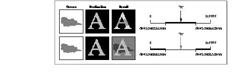
Note in Figure 53 that, when deviceMinimum is less than deviceMaximum , only the letter "A" in the destination image is within the destination limits, so the source is blended with the destination image only within the limits of the "A" to create the result. Conversely, when deviceMaximum is less than deviceMinimum , the "A" is outside the destination limits, so it is the only part of the destination not blended with the source to create the result.
The clampMinimum and clampMaximum fields in a color component's gxTransferComponent structure define the allowable range of values for the result color in that component. Color values outside of the range are pinned to the nearest clamp limit. If clampMaximum is less than clampMinimum , the range allowed consists of values less than clampMaximum or greater than clampMinimum . Figure 54 shows the effect of clampMinimum and clampMaximum on drawing using blend mode.
Figure 54 The effect of result color limits on drawing
Note in Figure 54 that, when clampMinimum is less than clampMaximum , extreme color values cannot occur in the result. The portions of the "A" outside of the cloud are darker than they would normally be with blend mode, and the portions of the cloud outside of the letter are lighter than they would normally be. Conversely, when clampMaximum is less than clampMinimum , midrange values are not possible in the result. The background in the result is lighter than it would normally be with blend mode, and the portions of the cloud outside of the "A" are darker than they would normally be.
Pinning restricts the value of the computation, not necessarily the value allowed for the actual pixel. The pixel value is the closest found to the computation, which may be outside of the range of clampMinimum and clampMaximum .
QuickDraw GX provides three matrices in the transfer mode structure to give you great freedom in controlling, modifying, and combining source, destination, and result color components when performing a transfer mode operation.
The source matrix, device matrix, and result matrix provide a way of scaling, weighting, swapping, and averaging the components of a color space before or after the transfer mode operation. Each matrix is a 5 4 array that specifies the mixture of each of the (up to 4) components, plus an offset.
An identity matrix, one that has values of 1.0 along the diagonal and zero values elsewhere, has no effect. Here it is applied to a color in CMYK space:
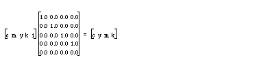
The values for all color components after the matrix multiplication are the same as before. All transfer mode matrices in the default ink object are identity matrices.
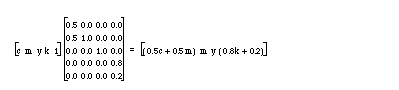
The bottom row of the matrix specifies an offset value. The following matrix replaces c with 1/2 c + 1/2 m; it also scales k by 0.8 and adds 0.2 to it:
The source and device matrix are applied before the transfer mode calculation and after applying source minimum and source maximum. The result of the transfer mode calculation is run through the result matrix. The use of matrices allows you to apply sophisticated mapping operations--analogous to the scaling, rotation, translation, and distortion of shapes--to the colors involved in a transfer mode operation. Matrices are also used to create color separations, and to map source color ranges to spot colors.
Although color components are described by unsigned shorts (16-bit positive numbers), the math internal to transfer modes is performed with longs (32-bit signed numbers) to minimize overflow or roundoff error. As an example, elements in the source matrix could multiply by a large number, and elements in the result matrix could divide by a large number, without creating an overflow condition.
QuickDraw GX provides two sets of flags in the transfer mode structure that control certain aspects of the transfer mode operation. One set operates on individual color components; the other set operates on the source or destination color as a whole, taking into account all of the components.
The transfer component flags are a set of flags in the gxTransferComponent structure (in the component field of the transfer mode structure) that alter the source, destination, or result value for an individual color component. There are two constants for these flags, defined in the gxComponentFlags enumeration:
|
QuickDraw GX performs an AND operation between the result color and 0xFFFF before clamping. |
||
|
QuickDraw GX reverses the source and destination values before performing the transfer mode operation. |
Specifying gxOverResultComponent allows the result of transfers using gxAddMode to wrap around (from 0xFFFF to 0x0000 ) instead of remaining clamped at 0xFFFF .
Specifying gxReverseComponent allows you to apply a transfer mode backwards--from the destination to the source--for a particular component. It is most useful for component modes that depend on order, like gxMigrateMode , or gxAddMode when used for subtraction.
The transfer mode flags are a set of flags in the flags field of the transfer mode structure. They affect how color limits are used and whether a single component mode is to be used for all color components. There are three values for the flags, defined in the gxTransferFlags enumeration:
Setting the gxRejectSourceTransfer or gxRejectDeviceTransfer flag causes an inversion of the acceptable color ranges for source or destination color, respectively. For example, in Figure 51 , setting the gxRejectSourceTransfer or gxRejectDeviceTransfer flag would cause the white (empty) portions of the large cubes that represent RGB space to be within range, instead of the gray (filled) portions.
The effect is similar to, although not exactly the same as, individually reversing the minimum and maximum values for the color components. If the transfer mode flag is cleared, drawing occurs only when all components are inside the allowed ranges--that is, inside the darker gray portions of the large cubes in Figure 51 . With the flag set, drawing occurs any time at least one component is outside of its allowed range--that is, with values anywhere outside of the dark gray areas in Figure 51 .
The gxSingleComponentTransfer flag is provided as a convenience. You can set the flag when you don't need the flexibility (and extra effort) of specifying different transfer modes for different color components. In this case you need set up only one gxTransferComponent structure, instead of one for each component in the transfer mode's color space.
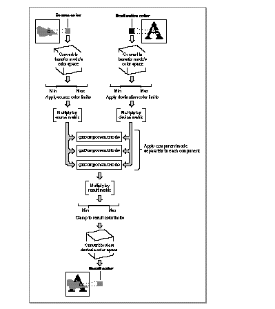
Figure 55 shows how all the parts of the transfer mode structure work together when a color is drawn.
Figure 55 Summary of transfer mode operation